
Tutorial: POV‑Ray forested scene output
Leveller and Landshaper Golf can render their own foliage objects, but interfacing to POV‑Ray is useful as it is a more general-purpose system.
POV‑Ray 3.1 and higher include support for arrays, allowing simplified management of the thousands of object locations a forest scene needs. However, it takes a front-end program (in this case, Leveller), to initially generate those locations and to create a usuable POV‑Ray scene description.
It's assumed you're already a bit familiar with POV‑Ray.
Step 1: Create the terrain
Step 2: Color the terrain
Step 3: Set up the scene
Step 4: Choose the location of the trees
Step 5: Output to POV‑Ray
Step 6: Edit the POV‑Ray scene file
Step 7: Render
Step 1: Create the terrain
After starting Leveller, choose Edit, Resample, 128 x 128 to make a small but serviceable heightfield. Then choose the Filter, G-L, gforge... command to make some hills. The height value should be set to around 20. In our case, we used the Raise tool with several brush sizes to make a peak in the east side.
While larger heightfields will yield more realistic results, it's always good to practice with a small heightfield first. This way, you won't spend a lot of time waiting for the computer to process things while you experiment.
You could import a DEM or GIS elevation file as well, which instantly provides realistic terrain. For our example, we wanted a soft look, so we decided to modify some gforge output since DEMs usually look rougher.
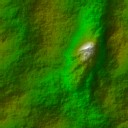
Step 2: Color the terrain
We changed the default colormap to the 'Earth' style using the View, Colormap... command. To get a bit more realism, however, you can apply a bitmap texture with the View, Texture... command. If you're going to create the type of dense forest that obscures most of the ground, coloring the terrain might not be an issue. For our example (which has a fair bit of open spaces), we opted to blend an aerial photo with the colormap, as shown below.
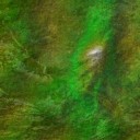
Since POV‑Ray doesn't support imagemaps and colormaps in a heightfield's pigment attribute at the same time (as far as we know, anyway), we simply used a paint program to blend the two manually, and applied the result as an imagemap. If the terms sound confusing; don't worry -- all the POV‑Ray scene code will be shown and explained later on.
Step 3: Set up the scene
Using the Light tool, place the light source at a better position than the default location of (0, 50, 0), which is usually too close for landscape heightfields. The light position, of course, can always be changed later by editing the POV‑Ray scene file.
Move the camera to a good viewing location. You may also want to use the Window, Resize Scene submenu to size the 3D scene window to an aspect ratio similar to what POV‑Ray will use (e.g., 4:3).
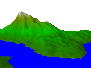
For our example, we placed the camera on the west side of the map looking east and slightly south. This places the peak nicely off-center and in the background, while giving a good view of the foothills where most of the trees will be. We set a water level as well, since it makes the scene more interesting. The picture above was rendered directly by Leveller, but the final scene will be rendered by POV‑Ray, so we don't worry about what it looks like for now. We also set the scene size to 320 x 240, to match the aspect ratio of the 640 x 480 window POV‑Ray will render to.
Step 4: Choose the location of the trees
Using one of the selection tools, drag the mouse on the overview map to select the area where you want the forest to be. Rectangular and ellipitcal areas will probably look too artificial, so a more natural-looking choice is to use either the Arbitrary Select or Magic Wand tool. Holding down the Shift key while repeatedly using these tools will let you extend the selected area.
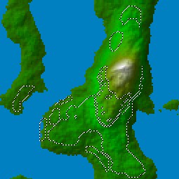
For our forest, we started with the Magic Wand tool to select areas near the peak, then switched to the Arbitrary Select tool to include chunks of land in the foreground near the camera. One simple trick to avoid selecting too many points is to simply limit yourself to the area that the camera can see. The north part of the western island, for instance, we didn't bother with, since it won't be visible. The same goes for the eastern shore of the main land mass, since it's obscured by hills.
Since trees tend to not grow on steep areas, you can use the Selection, Plug-ins, Select Slopes... command to select areas of gentle slope.
If you go to a lot of trouble to make the selection, it's a good idea to save it with the Selection, Save Selection... command.
Step 5: Output to POV‑Ray
Choose the File, Output, POV‑Ray... command. This displays the POV‑Ray output dialog. In the Include section, check the Selected map area as point array box on, and click the Settings... button underneath it. This brings up a dialog box letting you specify how you want the trees to be positioned within the selected area:
It's easy to create an orchard-type look where all the trees are evenly spaced apart in regular rows and columns. For a forest, though, we usually want more random locations. To do this, use lower values for the Probability field. Some experimenting with low probabilities and low spacing values may be needed to get just the right look.
A good choice to start with is 0.5 for the spacing, and 10 percent for the probability. On average, the trees will be 5 heightfield pixels apart from each other. Since our heightfield is only 128 x 128 pixels in size, however, we'll probably lower the spacing, to bring the trees closer together. One nice thing about POV‑Ray is that, since it includes conditional programming constructs, you can generate lots of tree locations, and simply filter them to use only a few of them for quick test renditions (we'll show an example in the POV file later on).
Close the dialog. In the main POV‑Ray output dialog, check the Include heightfield option on. Otherwise, the forest will appear but the terrain won't. After choosing values for the other settings, click OK to create the POV‑Ray file. You can give different names for the heightfield's TGA file and the POV‑Ray scene file, but it's handy to make them the same (e.g., "island.tga" and "island.pov"), to keep track of them later on. The texture bitmap we created in step 2 we've called "island_texture.tga".
Since our scene includes water, we could have also checked the Exclude points option to make sure that none of the trees would be in the water. But in our case, we wanted to have a few trees drawn that way, because sometimes that happens in nature.
Step 6: Edit the POV‑Ray scene file
Start POV‑Ray, if it isn't open already, and use its File, Open command to open the scene (.pov) file you just exported.
Although we could have asked Leveller to include a sample script to use the exported array of tree locations, it would have shown each tree as a sphere, but we need trees that, well, look like trees. To do this, download (if you haven't already) the veg.inc file from the Genesis Toolkit, and add the following lines of text to the scene file:
#include "veg.inc"
#declare R = seed(0);
#declare N = 0;
#declare FILTER_PCT = 25; // Increase this to show more trees (up to 100 %)
#while(N < HF_pts)
  #declare TT = rand(R) * 100;
  #if(TT < FILTER_PCT)
    #declare H = rand(R) * 1.5 + 3; // Tree's height
    #declare XZ = rand(R)/3 + .33;  // Tree's diameter
    #declare YOFF = rand(R) * -1;   // Vertical jitter
    object
    {
      Tree2 scale <XZ, H/10, XZ>
      translate HF_pts_array[N]
      translate y*YOFF
    }
  #end
  #declare N = N + 1;
#end // while (more trees to draw)
The Genesis include file is only an example, of course. If you have your own tree objects, you may want to use them instead. Our example assumes that the veg.inc file is in the same directory as the scene file, or is somewhere in POV‑Ray's include file search list.
Because the scene file contains the tree location array, it will be fairly long, depending on how much of the heightfield you selected in step 4. Pressing Ctrl-End will take you to the bottom of the file immediately. Our example code uses 25 for the FILTER_PCT value; this will let only 25% of the trees be drawn so that we can do a quick test rendition while still getting an idea of the area coverage. The scaling factors used for the Tree2 object were chosen with a 128 x 128 sized heightfield in mind.
If you render the scene at this point, it will show trees, but the land, water, and sky will look flat. We'll modify the heightfield instruction block near the top of the file to use the texture bitmap we created in step 2. Below is how the block should read:
height_field
{
  tga "island.tga" // Your elevation TGA filename may differ
  smooth
  texture
  {
    pigment
    {
      image_map
      {
        // Your texture bitmap filename may differ
        tga "island_texture.tga" map_type 0 interpolate 2 once
      }
      rotate x*90 // lay X-Y image map down onto X-Z height field plane
    }
  }
  finish { ambient .2 }
  // The next two lines may be different in your case
  translate <-.5, 0.034, -.5>
  scale <127.000, 42.591, 127.000>
}
How about the sky and the water? In our case, we went with the following:
// Our water is a modified version of Robert Becraft's river surface example
// described in his February 22/99 c.g.r.r. posting.
plane
{
  y, 13
  texture
  {
    pigment { color rgb < 0.3, 0.3, 0.7 > }
    normal { bumps 0.2 scale < .5, 0.25, 0.15 > }
    finish { phong 1 reflection 1.0 ambient 0.2 diffuse 0.2 specular 1.0 }
  }
  translate < 0, .20 , 0 >
}
// Our sky is just a sky sphere with a light blue to dark blue gradient.
sky_sphere
{
  pigment
  {
    gradient y
    color_map
    {
      [0.00 color rgb <.6,.6,1> ]
      [0.05 color rgb <.5,.5,1> ]
      [1.00 color rgb <0.2,0.2,1.0> ]
    }
  }
}
Step 7: Render
In POV‑Ray, choose a rendering window size, and press Alt-G to render the scene. As with all scenes, some tweaking of the light source and object surface attributes (ambience, specularity, texture, etc.) may be needed to get everything perfect.
Once you've got things looking right, simply change the FILTER_PCT variable to include any missing trees, and render the final image. The examples here were done at 640 x 480, antialiased.
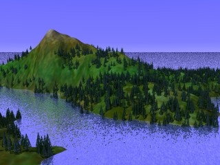
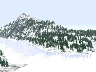
Here's our first result. It's dominantly blue, so to soften it we added some fog (see below).

Fog added using:
fog
{
   fog_type 1
   distance 200
   color <.85,.9,1>
}
gforge bump mapping used on the terrain and water. Trees below the water were culled.
Click here to see the full-size image.
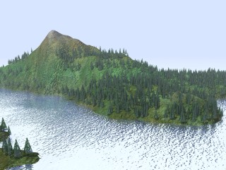
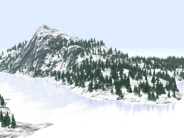
A fractal plasma bump map in the Superpatch version of POV 3.1a does slope-based coloring. The trees' rotation around the Z axis was jittered slightly to increase naturalness, then the image was despeckled, sharpened, and given a slight contrast boost.
Click here to see the full-size image.
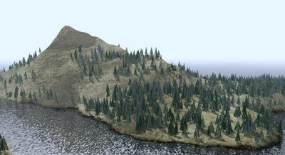
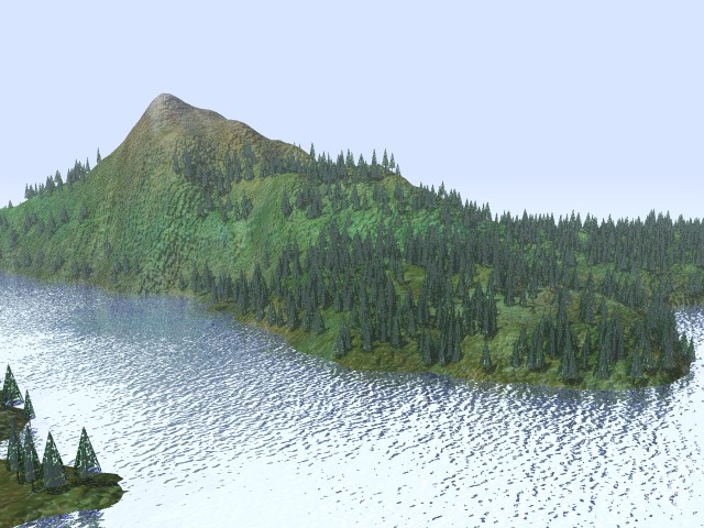
Terragen generated the imagemap which was then mapped on the heightfield's vertical axis to lend a stratified look.
Click here to see the full-size image.
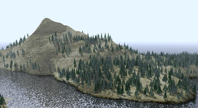
The light source was moved to make the land and trees cast shadows, and the shoreline was darkened in a bitmap editor. The trees were spun around their Y axes randomly, and lighter versions were added.
Trees are not the only objects that can be placed around, of course. With some simple changes to the code in step 6, rocks, bushes, and other types of trees could be added.